Ironridge Ground Mount Design Tool
● Click the Tab Above ⇑ Alternative Spread Footer, Videos & Documents to Learn More About Ground Mount Racking.
IronRidge Ground Mount; Stronger Using Less Material, Faster Installation

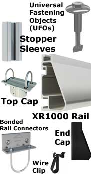
What's On the Truck
- IronRidge XR1000 Ground Rack Kit Configured in Landscape 3 - 5 High Layout for Wind Speed and Ground Snow Load for the Most Common Values Associated with Your Project Location. 1 Rack Set Per Panel (IE: 10 Panel Kit Requires 10 Rack Sets)
- 2 IronRidge XR1000 Rails Per (column) 3 - 4 or 5 High Set (Panels, Landscape Orientation Only) Clear Finish
- IronRidge, Universal Fastening Objects (UFOs), Black or Clear to Match Module Frame
- IronRidge, Universal Fastening Objects (UFOs) Stopper Sleeves, Black or Clear Finish to Match Module Frame. The IronRidge Integrated Grounding System bonds solar module frames directly to the mounting rails. This eliminates the need for separate module grounding parts and procedures.
- IronRidge, SGA Top Cap, for 3" pipe, 70-0300-SGA Clear Finish for 110 MPH Wind Structural Load Rating # Depends on # Piers
- IronRidge, Bonded Rail Connectors, for 3" pipe, GM-BRC-003 Clear Finish 1 Per Module
- IronRidge, Wire Clip, for XR Rails, for (10) 5mm panel wires, or (1) MC4, (1) Enphase wire and (1) dual Enphase wire, PVC plastic, Qty. 1 bag of 20 pieces, 29-4000-077 1 Per Module
- IronRidge, End Cap XR1000, Qty. one bag of 10 Sets, XR-100-CAP; 1 for Each Rack End, # Depends on Racks
- Included as Code Requirement for your Racking Configuration; IronRidge Grounding Lug, Low Profile (Qty 2), GD-LUG-003.
- (3" Schedule 40 Pipe Not Included. Locally Sourced)
![]() NOTE: 5 high Configuration Can Only be Constructed with 3" Schedule 40 Pipe Because 2" Pipe 5 High Exceed Project Load Conditions of Standard Ground Array Capabilities. The same may be true of high ground snow and or wind load areas of the country.
NOTE: 5 high Configuration Can Only be Constructed with 3" Schedule 40 Pipe Because 2" Pipe 5 High Exceed Project Load Conditions of Standard Ground Array Capabilities. The same may be true of high ground snow and or wind load areas of the country.
![]() If you are ordering the IronRidge pre-configured racking solution but supplying your own solar panels [Not Purchased from BPS], you will need to note in the checkout process at "SHIPPING PREFERENCES - Special instructions about delivery:" the solar panel manufacture and model number of the panel you intend to use so we can size the end clamp stopper sleve accordingly.
If you are ordering the IronRidge pre-configured racking solution but supplying your own solar panels [Not Purchased from BPS], you will need to note in the checkout process at "SHIPPING PREFERENCES - Special instructions about delivery:" the solar panel manufacture and model number of the panel you intend to use so we can size the end clamp stopper sleve accordingly.
![]() Per NEC 2017 code 690.31(A) and 110.27(A) PV wires under the ground array need to be guarded against accidental contact. Check with your local AHJ (Authority Having Jurisdiction) for your local requirements. If required, in our experience chicken wire over the PV wire on the back side of the array runs the cheapest and easiest solution. Other options may include a low fence around the perimeter of the array.
Per NEC 2017 code 690.31(A) and 110.27(A) PV wires under the ground array need to be guarded against accidental contact. Check with your local AHJ (Authority Having Jurisdiction) for your local requirements. If required, in our experience chicken wire over the PV wire on the back side of the array runs the cheapest and easiest solution. Other options may include a low fence around the perimeter of the array.
A question we often get asked is my soil is very rocky. Do you have any foundation designs aside from concrete pier footings? IronRidge provides standard foundation sizes for various soil classes. However, some soils may be extremely difficult to dig into, such as granite or rocky soils. A alternative solution for these soil types would be having us engineer a spread footer. Consult an engineer for structural review if using a foundation design other than those described in the IronRidge Certification Letters. (NOTE: Engineering spread footer requires the addition of the optional Blue Pacific Solar® Permit Document Service with the Optional Structural Engineering Review & Wet Stamp.)

Ironridge Ground Mount Design Tool
Source: https://www.bluepacificsolar.com/home-solar/ironridge-ground-mount.html
Posted by: terwilligerbervicad.blogspot.com

0 Response to "Ironridge Ground Mount Design Tool"
Post a Comment